Building the W3NQN Passive Audio Filter
(a link to download the Word doc is at the bottom of the page)
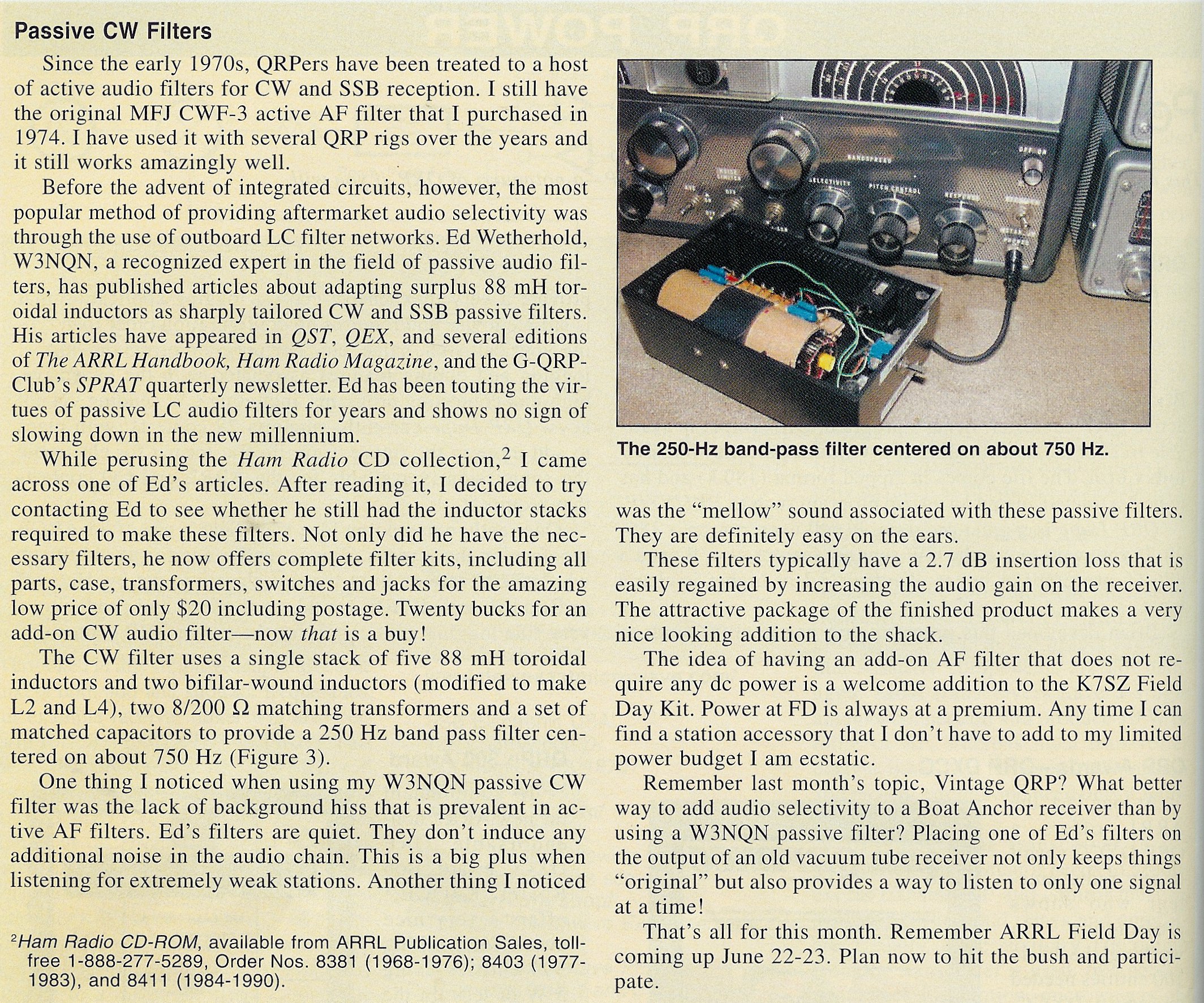
The May, 2002 QST, page 96 (QRP Power) mentioned a neat item, called a passive audio filter. I’d heard of these, but never used one. I emailed Rich, K7SZ, editor of the QST QRP column, and he suggested I contact Ed, W3NQN directly. Well, I wrote to Ed, and he replied with a nice letter and the cost of the filter kit, which is $45 postpaid (make checks payable to Ed Wetherhold).
Figure 1 – Here are the contents of the kit:
Included are the box, predrilled, with the in/out switch and phone jack (¼-in, mono) installed and a piece of ribbon cable that you pull apart for interconnections. A 5-inductor stack (shown above the phone plug and cable in Figure 1) is used for L1, L3 and L5, and the two separate toroidal inductors (bottom right of Figure 1) are for L2 and L4. Also included are input and output transformers, rubber feet, a ¼-inch mono-phone plug with a 34-inch cord, and a small manila envelope with capacitors and resistors. All the parts you require are there, including complete instructions for assembly. Be sure to read thru the instructions first and refer to the schematic and pictorial diagrams to find the node locations listed in Table 1.
Assembly is easy. First, jumper the wires on the toroid stack, I used bare copper wire. Then I had to scrape off the enamel-film insulation from the wire ends of the two separate inductors (specified as L2 and L4 in Table 1) before mounting them on the ends of the stack and wiring them to the stack terminals. For the 550Hz filter it was not necessary to remove turns from these two inductors, but for filters having higher center frequencies, L2 and L4 require turns-removal modification. They are secured to the stack with GE Household Glue, 100% Silicone Sealant, Clear, 2.8 Fl.Oz (available at your local hardware store). Then just wire up the capacitors to the stack. Two of them are held to the stack with the above mentioned silicone glue. The input and output capacitors are supported by their leads. When this ‘stack’ is finished, you make ohmmeter readings to make sure it’s wired correctly. The readings are +/- 20% and I modified Ed’s chart to indicate the high, low and nominal readings. It makes it easier than to calculate the 20% in your head!
| Nodes From To |
COMPONENTS | -20% | RESIT (ohms) |
+20% | |
| 1 | GND | T1 Hi-Z Winding | 9.6 | 12.0 | 14.4 |
| 2 | GND | L1 + 1/2(L2) | 8.6 | 10.7 | 12.8 |
| 3 | GND | L2 | 6.4 | 8.0 | 9.6 |
| 4 | GND | 1/2(L2) | 2.2 | 2.8 | 3.4 |
| 5 | GND | L3 + 1/2(L4) | 20.6 | 25.8 | 31.0 |
| 6 | GND | 1/2(L4) | 2.2 | 2.8 | 3.4 |
| 7 | GND | L4 | 6.4 | 8.0 | 9.6 |
| 8 | GND | L5 + 1/2(L4) | 8.6 | 10.7 | 12.8 |
| 9 | GND | T2 Hi-Z Winding | 9.6 | 12.0 | 14.4 |
| 2 | 4 | L1 | 6.4 | 8.0 | 9.6 |
| 5 | 6 | L3 | 19.2 | 24.0 | 28.8 |
| 6 | 8 | L5 | 6.4 | 8.0 | 9.6 |
| 2 | 3 | L1 + 1/2(L2) | 8.6 | 10.7 | 12.8 |
| 8 | 7 | L5 + 1/2(L4) | 8.6 | 10.7 | 12.8 |
Table 1. Node-to-Node resistances for the 750-Hz filter assembly
(Refer to note 1 at the end of the article)
Once all resistance readings are correct, you wire up the input and output transformers with some wire from the ribbon cable provided in the kit. Mount them to the case with more silicone glue and wire them up to the input cable and output jack. Connect the transformer secondary to their respective capacitors and you’re almost there. The toroid stack presses into a clip that’s already mounted in the box. A resistor on one side of the switch is used to match the volume, so when the filter is ‘out’ you don’t get your ears blasted. There is some insertion loss, so, just turn up the volume. I put a pot across the switch terminals, and adjusted it, so the volume was the same for either position of the switch (I used my scope and audio generator) and then measured the pot and substituted a fixed resistor (mine was 44 ohms). Now you’re done.
The supplied in/out switch is a center-off, DPDT unit. I was considering replacing it with a normal DPDT (no center-off). But, I soon learned that the center position, which cuts out all audio, is useful, especially if the XYL comes into the shack (and you want to listen to what she says). Ed has since replaced this switch with an on-on type, no center off position.
Figure 2 - The completely assembled filter.
The toroid stack is mounted in its clip on the left. The input and output transformers are on the lower part of the box, along with the in/out switch. The input cord and output jack are on the lower right.
How does it work?
When I hooked it up to my Kenwood TS-570D(g), the background noise almost disappeared. Since this unit is passive, it does not introduce any noise of its own. Great for Field Day and portable work, although it will add weight and be larger than many QRP radios! Tune through the bands with the filter out. When you hear a signal of interest, switch it in. The signal will stand out and all you hear is that signal. It is remarkable. Figure 3 shows the attenuation response when the filter is measured in a 200-ohm test system (less the input and output transformers).
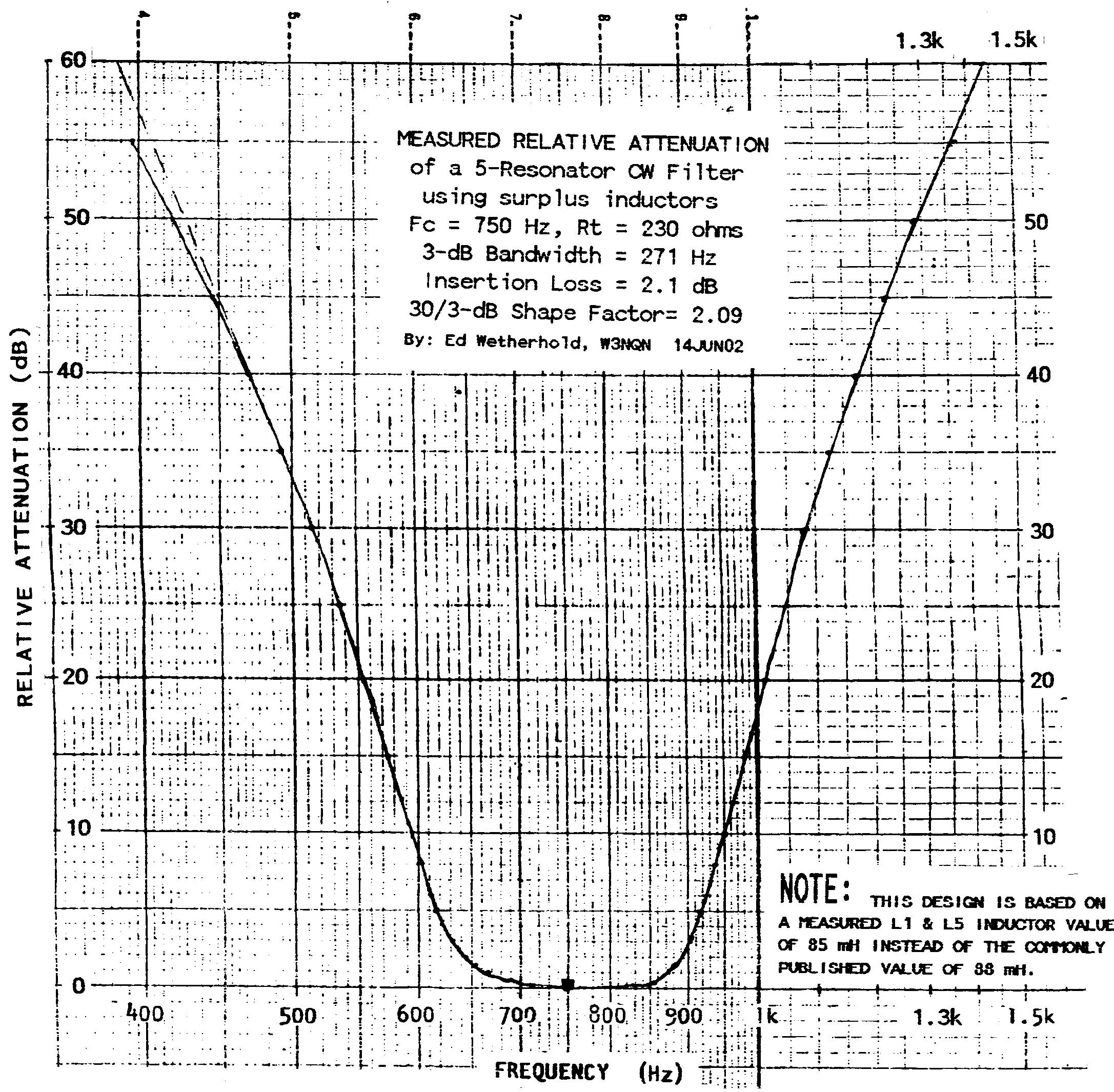
Figure 3 – Measured relative attenuation of the cw filter.
And HOW does it work?
The passive audio filter ‘reduces wide-band noise and restricts the audio bandwidth of the receiver’ (from the 1985 Handbook). The Handbook describes a 10-element Chebyshev band-pass filter, using telephone-type toroids, which are supplied. The center frequency of the filter should match the sidetone frequency of your receiver. Remember, get the correct filter for your sidetone frequency, otherwise you will not hear your sidetone. I verified this on my TS-570 and Elecraft K2, its true! The filter is very sharp. Just to make the point again, if your sidetone is 550 Hz and you have a 750 Hz filter (center frequency), the sidetone will be attenuated by 20dB. Currently available center frequencies are 546, 600 and 750 Hz. Contact Ed if you require a different frequency. Filters for SSB operation are also available.
You can contact Ed at:
Ed Wetherhold, W3NQN
1426 Catlyn Place
Annapolis, MD 21401-4208
for more information. If you require a reply, please send him a 9½x4 inch SASE. Please type (or hand print) your correspondence, and include the date, your name, address and phone number. Ed also asks that you do not use any of the small self-stick labels, normally used for return address labels. You may fax to Ed at 410-268-4779 or contact him by phone at 410-268-0916.
Ed has articles and correspondence in QST and QEX, from July 1966 through June 1998. These cover both audio and RF filter design.
The 1985, 1994 and 1995 ARRL Handbooks, have a section on Ed and his passive filter designs, as does Bill Orr’s Radio Handbook (see Note 2). Ed has also designed RF filters, sold by Array Solutions at: www.arraysolutions.com.
73, Ken WB2ART, FISTS #3456
wb2art (at) arrl (dot) net
(With kind assistance from Ed Wetherhold, W3NQN)
Note 1: To find the node points in the filter wiring of the inductor stack, refer to the schematic and pictorial diagrams that are provided with the filter kit assembly instructions.
Note 2: Bill Orr’s Radio Handbook, 23rd edition, p. 13-5, published by Howard W. Sams & Co., First Printing – 1986.
Download the original doc in Word format.
Original blurb in May 2002 QST.
![]()
© Ken Kaplan WB2ART 2006